
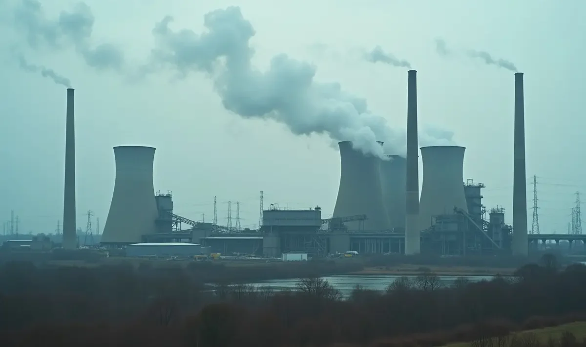
A coal-fired plant is a heat engine with a coal yard at one end and a switchyard at the other. Everything between those points turns chemical energy into electrical energy in four main steps. Once you understand that chain, each large component has a clear job.
Energy first, parts second
Chemical energy sits in the coal. Burning releases it as heat in the furnace. That heat makes high-pressure steam, which expands through a turbine to spin a shaft. The generator then turns that shaft rotation into electrical current.
That sequence describes the whole plant. The pump, boiler, turbine and condenser form the Rankine cycle, which repeats without pause. Feedwater is pressurised and boiled, steam is superheated and expanded, then exhaust steam is condensed and pumped back to the boiler for another pass.
Designers pursue small gains at each link. Less moisture in coal means more heat per tonne. Higher steam pressure allows more work per kilo of steam, while a tighter vacuum at the exhaust produces a larger pressure drop across the turbine.
Heat is the bottleneck.
From mine face to fine powder
It starts with mining. Raw coal leaves the pit with rock and water mixed through it. A coal handling and preparation plant cleans much of that material out. It washes away mineral matter and sorts the coal into sized products for shipment. Blending then steadies the quality so the power station receives a consistent feed day after day.
Calorific value is the number both sides watch closely. It indicates how much heat a tonne holds. Ash content shows how much inert material will pass through the furnace and leave as ash, while moisture indicates how much heat will be lost drying the fuel in the flame. When calorific value slips, fuel flow must rise to hold load. When ash climbs, mills wear faster and the plant must handle more residue.
At the station, the coal is crushed and then milled. Pulverisers grind it to around 75 microns, close to the consistency of talcum powder. Fine grinding matters because it opens up more surface area. That extra surface allows the fuel to ignite quickly and burn in suspension like a gas flame. It also leaves less unburned carbon in the ash and helps maintain flame stability.
Coarse particles cause trouble. They burn slowly and can drop out as slag on walls and hoppers. They increase fuel use per megawatt-hour and create more maintenance work around the burners. Mills and burners therefore receive plenty of attention from operations teams. They may not look impressive beside a turbine, but they influence how cleanly and efficiently the rest of the plant can run.
The boiler turns water into superheated steam
Pulverised coal rides a stream of hot air into the furnace. In most large units, it burns in suspension with no grate or fixed bed. Flame temperatures sit around 1,300 to 1,500C. The flame is the heat source, and its shape and length determine how evenly the furnace walls absorb that heat.
Water-wall tubes line those furnace walls. Feedwater pumped to high pressure flows through the tubes and absorbs heat until it boils. Saturated steam then passes through superheater banks in the hotter gas path. Superheating raises it well above the boiling point at that pressure, producing what is known as superheated steam. Reheaters perform the same task after steam has passed through the first turbine stage, helping the remaining expansion stay dry and forceful.
Superheated steam contains more usable energy per kilo. The hotter it is, the more work the turbine can extract from the same mass flow. Advanced plants push steam towards 600C because each additional increment reduces coal burn. Tubes and valves set the practical limit, since they must withstand pressure and heat for years without creep or cracking.
The boiler also functions as an air and gas machine. Fans push combustion air in, while other fans pull flue gas out through filters and scrubbers. Controls keep fuel and air balanced across different loads. Too little air leaves carbon unburned in the ash. Too much carries heat up the stack and reduces operating margins. Operators monitor both sides carefully, as small adjustments here can save tonnes of coal over a week.
Turbines and generator turn steam into current
High-pressure steam reaches the turbine first. It expands through the high-pressure and intermediate-pressure stages, with reheat between them to keep the steam dry and energetic. It then enters the low-pressure section, where the blades become longer to handle the large volume of low-density steam.
Each stage pairs fixed nozzles with moving blades. Pressure falls step by step, and steam velocity becomes torque on the shaft. The shaft spins at 3,000 rpm on 50 Hz systems. That speed is locked to grid frequency and does not drift during normal operation.
The generator sits on the same shaft line. Its rotor carries a magnetic field that sweeps past the stator windings, inducing alternating current in them. This is where mechanical energy becomes electrical energy. Nothing burns or boils in the generator. The process is based on rotation and magnetism, maintained within tight vibration and cooling limits.
Output leaves the generator at a modest voltage, and a transformer steps it up for transmission. High voltage keeps line losses low over long distances. Protection and controls surround the unit. Although they do not produce power, they allow it to leave safely and trip the unit quickly when pressures, temperatures or electrical faults move outside acceptable limits.
Condenser and cooling tower close the loop
Exhaust steam leaves the turbine with little pressure remaining. It enters the condenser, where cooling water flows through thousands of tubes. The steam meets the cold surface and collapses back into water. This change maintains a vacuum at the turbine exit.
Vacuum matters greatly. A tight vacuum creates a larger pressure drop across the turbine, allowing more work from the same steam. Air leaks or fouled tubes can spoil it quickly. Crews watch condenser pressure like a vital sign because losing even a few kilopascals appears immediately as a higher heat rate.
The cooling circuit must remove surplus heat that the cycle cannot use. About two-thirds of the fuel’s energy ends up here in a conventional steam cycle. Cooling towers reject that heat to the air, giving the condenser a steady supply of cool water.
Two designs dominate. Natural-draft towers are the tall, curved stacks that draw air by buoyancy without fans. Forced-draft towers use fans and sit lower and wider to suit the site layout. Both perform the same thermodynamic job, with the choice depending on water supply and available space.
Efficiency comes from pressure, temperature and coal quality
Subcritical plants run near 33 to 37% efficiency in normal service. Feedwater pumped to very high pressure moves through furnace walls and superheater banks operating near material limits. Each extra degree of superheat adds useful work, which appears directly as lower coal burn per megawatt-hour. Supercritical units built for those conditions reach 40 to 42%. Ultra-supercritical designs using still hotter steam push past 45%.
Above 22.1 MPa and 374C, water passes its critical point. There is no sharp boil, and water changes to steam without a distinct phase transition. This allows designers to use once-through boilers and run hotter without drum limits. The metals and control systems must be better to survive those conditions. The return is lower fuel use and lower emissions per megawatt-hour. IEA analysis found that lifting average coal plant efficiency from around 33% to 40% would cut CO2 by roughly one-fifth (IEA).
To understand how does a coal fired power plant work in practice, it is also necessary to examine fuel quality upstream. Heat rate depends heavily on what arrives by rail or conveyor, not only on turbine design.
Low calorific value requires a higher mass flow for the same power output. High ash loads the mills and the ash plant. High moisture consumes heat to dry the fuel in the flame and cools combustion. Mine planners and fuel buyers manage these traits together, while wash depth and blend ratios shift costs between the pit and the station. Mining and generation operate as one connected system. Improvements upstream appear as steadier combustion and reduced wear downstream.
Cleanup, ash and flexible operation
Flue gas leaves the boiler dirty. Cleaning it is part of normal operation, carried out alongside power production rather than treated as an extra process that can be skipped.
Dust, sulphur, nitrogen and mercury
Particulates come out first. An electrostatic precipitator charges fly ash particles and draws them towards collection plates. On some units, a baghouse performs the same task using fabric filters. Removal is very high when either system is properly maintained. Clean plates and intact bags matter more than brand names, while rapping cycles and pressure-drop trends show crews when action is needed.
Sulphur dioxide is next. Most large plants use wet flue-gas desulfurisation. Limestone slurry is sprayed into the gas stream, where it reacts with SO2 to form gypsum. Reagent feed and pH control determine the removal rate. Where markets exist, the gypsum can be sold, turning part of the reagent cost back into revenue.
Nitrogen oxides require a different approach. Selective catalytic reduction injects ammonia ahead of a catalyst bed. The catalyst converts NOx into nitrogen and water vapour. The temperature window is narrow, and burner tuning affects what enters the system. Operators manage load and excess air to maintain high conversion without causing ammonia slip.
Mercury arrives in a small mass but still requires care. Activated-carbon injection places a sorbent in the gas path. It captures mercury for removal downstream with ash in the precipitator or baghouse. Testing determines the dose rate for each coal blend, as no single setting suits every fuel.
Ash has two exits
Bottom ash drops from the furnace. It is coarse and gritty, requiring water handling for cooling and conveyance. Fly ash travels with the gas and is captured by the precipitator or baghouse. The streams remain separate because their uses and handling equipment differ.
Fly ash often goes into cement and concrete. It can replace part of the clinker in mixes that accept it, reducing waste volumes and giving the station a credit against disposal costs. Bottom ash goes into fill or construction products where specifications permit. Water handling and dust control complete the system. It is heavy work, and it continues every day without pause.
The operating role keeps shifting
Coal units were built for baseload service. They ran at steady output for long periods, with consistent heat rates and chemistry. That pattern still suits their design best because constant load keeps temperatures even and control systems relatively simple.
Grids with more renewables now demand greater flexibility. Load-following involves ramps and low-load holds that add thermal stress and reduce average efficiency. Plants can operate this way within limits set by thick-walled components and mill stability. Crews train for faster starts and low-load flame control. Maintenance plans also change, requiring more checks on headers, rotors and valves.
Mining remains part of this picture. Consistent size and quality help a unit ramp without flame loss or slag falls. Good stockpile management keeps blends stable through changes in demand. When the fuel varies, the controls must chase it. When the fuel remains steady, the whole loop is steadier.
Coal power looks bulky from the outside. Inside, it is a tight loop of pressure, heat and vacuum, with fuel quality setting the pace. When those four energy conversions work properly, the plant delivers steady output with lower waste.
